%GEOM Card
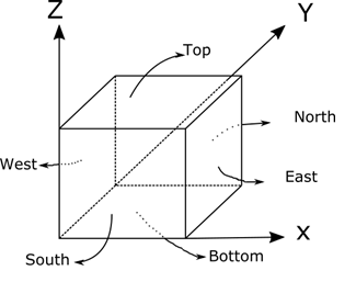
This card is used to describe the problem geometry in rectangular coordinate system. This card is mandatory. The coordinate system used in ADPRES is shown in the following figure

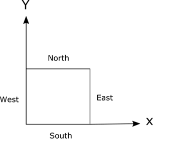
The point of origin is located at the corner between west, bottom and south sides. The next figure shows the coordinate system for radial planar map (seen from top) which typically used for two-dimensional problems.

Below you can find various %GEOM card examples for one, two and three-dimensional problems.
%GEOM |
Variable | Description | Remarks |
|---|---|---|---|
| LINE 1 | NX | Number of assemblies along X-direction | NX at least equal to 2 |
| NY | Number of assemblies along Y-direction | NY at least equal to 2 | |
| NZ | Number of assemblies along Z-direction | NZ at least equal to 2 | |
| LINE 2 | XSIZE(1:NX) | Assembly size along X-direction(from west to east) | |
| LINE 3 | XDIV(1:NX) | Assembly division along X-direction(from west to east) | |
| LINE 4 | YSIZE(1:NY) | Assembly size along Y-direction(from south to north) | |
| LINE 5 | YDIV(1:NY) | Assembly division along Y-direction(from south to north) | |
| LINE 6 | ZSIZE(1:NZ) | Assembly size along Z-direction(from bottom to top) | |
| LINE 7 | ZDIV(1:NZ) | Assembly division along Z-direction(from bottom to top) | |
| LINE 8 | NP | Number of different core planar with different material composition | |
| LINE 9 | ZPLN(1:NZ) | Planar assignment along axial or z-direction from bottom to top (see the example below) | |
| LINE 10 | ASM(1:NX) | Radial planar material map | Repeat this line NY times to form a core planar material map. Then, repeat this planar map NP times |
| LINE 11 | XEAST | East boundary conditions | 0 = Zero flux |
| XWEST | West boundary conditions | 1 = Zero incoming current | |
| YNORTH | North boundary conditions | 2 = Reflective | |
| YSOUTH | South boundary conditions | ||
| ZBOTT | Bottom boundary conditions | ||
| ZTOP | Top boundary conditions |
Example for 3D problem
Three-dimensional problem with 2x2 nodes per FA
! Typical %GEOM CARD for 3D problem with 2x2 nodes per FA
%GEOM
9 9 19         !nx, ny, nz
10.0 8*20.0    !x-direction assembly size in cm
1  8*2         !x-direction assembly divided into 2 (10 cm each)
8*20.0 10.0    !y-direction assembly size in cm
8*2  1         !y-direction assembly divided into 2 (10 cm each)
19*20.0        !z-direction assembly  in cm
19*1           !z-direction nodal is not divided
4              !np number of planar type
1  13*2  4*3  4     !planar assignment (from bottom to top)
! Planar_type_1 (Bottom Reflector)
  4  4  4  4  4  4  4  4  4            (LINE 10)
  4  4  4  4  4  4  4  4  4
  4  4  4  4  4  4  4  4  4
  4  4  4  4  4  4  4  4  4
  4  4  4  4  4  4  4  4  0
  4  4  4  4  4  4  4  4  0
  4  4  4  4  4  4  4  0  0
  4  4  4  4  4  4  0  0  0
  4  4  4  4  0  0  0  0  0
! Planar_type_2 (Fuel)
  3  2  2  2  3  2  2  1  4            (LINE 10)
  2  2  2  2  2  2  2  1  4
  2  2  2  2  2  2  1  1  4
  2  2  2  2  2  2  1  4  4
  3  2  2  2  3  1  1  4  0
  2  2  2  2  1  1  4  4  0
  2  2  1  1  1  4  4  0  0
  1  1  1  4  4  4  0  0  0
  4  4  4  4  0  0  0  0  0
! Planar_type_3 (Fuel+Partial Control Rods)
  3  2  2  2  3  2  2  1  4           (LINE 10)
  2  2  2  2  2  2  2  1  4
  2  2  3  2  2  2  1  1  4
  2  2  2  2  2  2  1  4  4
  3  2  2  2  3  1  1  4  0
  2  2  2  2  1  1  4  4  0
  2  2  1  1  1  4  4  0  0
  1  1  1  4  4  4  0  0  0
  4  4  4  4  0  0  0  0  0
! Planar_type_4 (Top reflectors)
  5  4  4  4  5  4  4  4  4           (LINE 10)
  4  4  4  4  4  4  4  4  4
  4  4  5  4  4  4  4  4  4
  4  4  4  4  4  4  4  4  4
  5  4  4  4  5  4  4  4  0
  4  4  4  4  4  4  4  4  0
  4  4  4  4  4  4  4  0  0
  4  4  4  4  4  4  0  0  0
  4  4  4  4  0  0  0  0  0
! Boundary conditions
! 0 = zero-flux
! 1 = zero-incoming current
! 2 = reflective
(east), (west), (north), (south), (bottom), (top)
   1       2       2        1        1        1
Example for 2D problem
Two-dimensional problem with 2x2 nodes per FA
! Typical %GEOM CARD for 2D problem with 2x2 nodes per FA
%GEOM
9 9 2                  !nx, ny, nz
11.5613   8*23.1226    !x-direction assembly size in cm
1  8*2                 !x-direction assembly divided into 2 (10 cm each)
8*23.1226 11.5613      !y-direction assembly size in cm
8*2  1                 !y-direction assembly divided into 2 (10 cm each)
2*11.5613              !z-direction assembly  in cm
2*1                    !z-direction nodal is not divided
1                      !np number of planar type
2*1                    !planar assignment (from bottom to top)
! Planar_type_1 (Bottom Reflector)
 1  8  2  6  1  7  1  4  3
 8  1  8  2  8  1  1  4  3
 2  8  1  8  2  7  1  4  3
 6  2  8  2  8  1  8  4  3
 1  8  2  8  2  5  4  3  3
 7  1  7  1  5  4  4  3  0
 1  1  1  8  4  4  3  3  0
 4  4  4  4  3  3  3  0  0
 3  3  3  3  3  0  0  0  0
! Boundary conditions
! 0 = zero-flux
! 1 = zero-incoming current
! 2 = reflective
(east), (west), (north), (south), (bottom), (top)
   1       2       2        1        2        2
Two-dimensional problem with 16x16 nodes per FA
! Typical %GEOM CARD for 2D problem with 16x16 nodes per FA
%GEOM
9 9 2                  !nx, ny, nz
10.0   8*20.0          !x-direction assembly size in cm
8  8*16                ! 16x16 per FA
8*20.0 10.0            !y-direction assembly size in cm
8*16  8                ! 16x16 per FA
2*1.25                 !z-direction assembly  in cm
2*1                    !z-direction nodal is not divided
1                      !np number of planar type
2*1                    !planar assignment (from bottom to top)
! Planar_type_1 (Bottom Reflector)
 3  2  2  2  3  2  2  1  4
 2  2  2  2  2  2  2  1  4
 2  2  2  2  2  2  1  1  4
 2  2  2  2  2  2  1  4  4
 3  2  2  2  3  1  1  4  0
 2  2  2  2  1  1  4  4  0
 2  2  1  1  1  4  4  0  0
 1  1  1  4  4  4  0  0  0
 4  4  4  4  0  0  0  0  0
! Boundary conditions
! 0 = zero-flux
! 1 = zero-incoming current
! 2 = reflective
(east), (west), (north), (south), (bottom), (top)
   1       2       2        1        2        2
Example for 1D problem
One-dimensional problem with 1 cm node or mesh size
! Typical %GEOM CARD for 1D problem with 1 cm node or mesh size
%GEOM
5 2 2                !nx, ny, nz
5*20.0               !x-direction assembly size in cm
5*20                 !x-direction assembly divided into 20 (1 cm each)
2*1.0                !y-direction assembly size in cm
2*1                  !y-direction nodal is not divided
2*1.0                !z-direction assembly  in cm
2*1                  !z-direction nodal is not divided
1                    !np number of planar type
2*1                  !planar assignment (from bottom to top)
! Planar_type_1 (Bottom Reflector)
 5 4 3 2 1
 5 4 3 2 1
! Boundary conditions
! 0 = zero-flux
! 1 = zero-incoming current
! 2 = reflective
(east), (west), (north), (south), (bottom), (top)
   2       1       2        2        2        2